Downloadable Charts to Understand Audio Signal Flow in a DAW
Understanding signal flow in DAW-based recording and mixing is vital for efficient music production. Learn the basics through two simple, downloadable charts.
Click below to download the charts in this article, showing signal flow in recording and mixing.
Understanding signal flow in DAW-based recording and mixing is vital for efficient music production. Unfortunately, it's not hard to get lost or misinterpret where your signals are going and when they hit different software and hardware elements of your setup. Confusion about these things can quickly lead to counterproductive actions, incomplete routing configurations, or even dangerous feedback loops.
Signal flow between components tends to be easier to comprehend when you can see cables connecting them. However, in a DAW, you are typically not provided that luxury as you're usually dealing with virtual connections that cannot be seen. So, it's not as easy as following a cable trail from device to device.
Although there are oodles of signal flow variations, none of them will make sense if you don't grasp the basics.
DAW signal flow for recording
I've seen a lot of slip-ups in recording sessions where people think a certain process or piece of gear is being recorded when it is really only being heard. Such mistakes can be avoided with a few facts planted firmly in your memory. Let's analyze a straightforward vocal recording setup with just the basics—a mic, audio interface, computer, and headphones.
Here's the signal flow:
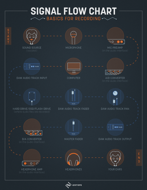
The recording signal flow
Two facts of supreme importance to keep in mind:
- The mic preamp is before the A/D converter. So, set your recording level via the mic preamp. If you cause distortion by overloading the A/D converter, turning down the track fader won't fix the distortion problem.
- The fader is after the hard drive (where the audio file is recorded). As a result, the track fader does not affect your recording level.
Plugging in plug-ins
People use plug-ins in recording sessions. So, let's add two plug-ins—a compressor and an EQ—to the vocal track in the previously outlined signal flow.
The plug-ins will be located in the insert positions, which are after the recorded audio on the hard drive, but before the fader. Furthermore, the plug-in in the first insert position (the compressor) will feed into the plug-in in the second insert position (the EQ). So, the resulting order is:
Hard drive > insert #1 (compressor plug-in) > insert #2 (EQ plug-in) > fader
Everything else about the basic signal flow remains the same.
Two crucially important facts to note about this order:
- The plug-in processing on the vocal track is not recorded to the vocal audio file, it is only being monitored.
- The order of the plug-ins matters. If the order is compressor then EQ, EQ changes will not impact the compressor. However, if the order is EQ then compressor, EQ changes will affect the compressor (EQ boosts will cause more compression, EQ cuts will cause less compression). One order is not inherently better than the other; each offers different benefits and drawbacks.
Some plug-ins, such as Ozone 9, have multiple modules, which can be rearranged. In the before and after images below, notice that the order and number of modules can be changed. There isn't a universally right or wrong order when it comes to plug-ins and processors, so experiment!

Simple processing chain in Ozone 9

More complex processing chain in Ozone 9
Get sent
Auxiliary sends (a.k.a sends) are used during recording sessions for purposes such as headphone mixes and reverb configurations because they can easily route a duplicate signal to a different destination than the track output. Remember that sends are duplicating (splitting) the signal and therefore do not affect the signal that is on the normal signal flow path in the track.
In this way, using a send differs from busing the output of the track. Granted, sends and buses are alike in that they allow you to route signal from one or more tracks to a common destination. However, whereas a send duplicates the original signal before or after the fader and doesn’t change the original signal’s output, busing the output of the track does not duplicate the original signal and instead changes the original signal’s output after the fader. As a result, buses are used primarily in mixing for summing tracks and routing to other tracks. Access to buses is at the track output, just after the pan.
As for sends, in they go to the signal flow!
Sends can generally be set to one of two positions, pre-fader or post-fader.
Pre-Fader: the send will be before the track fader. No matter what you do with the track fader, the send level remains the same. This is normally preferred when routing sends to headphone mixes because the send levels feeding to the artists won't be affected by level changes to the track faders. This allows separate mixes to be made for the engineer and one or more artists.
Post-Fader: the send will be after the track fader. Any level change to the track fader will affect the level of signal to the send. This is normally preferred when routing sends to time-based processors such as reverbs and delays because it allows the ratio of original to affected signal to remain fixed even as the main track fader is adjusted.
With the sends in place, the resulting signal flow order is:
Hard drive > insert #1 (compressor plug-in) > insert #2 (EQ plug-in) > pre-fader send > fader > post-fader send > pan
Everything else about the basic signal flow remains the same.
Two important facts about this order:
- The plug-ins (in the insert positions) affect what goes to pre- and post-fader sends. So, if you are going crazy with EQ changes, those tweaks will absolutely affect the signal to both pre- and post-fader sends.
- Sends do not affect the recording or the level going through the track fader. This means that you can adjust the send levels without impacting the main signal level in the track.
DAW signal flow for mixing
The signal flow for mixing is similar to and easier than the one for recording. With the addition of the inserts and sends, here’s the resulting signal flow for mixing:
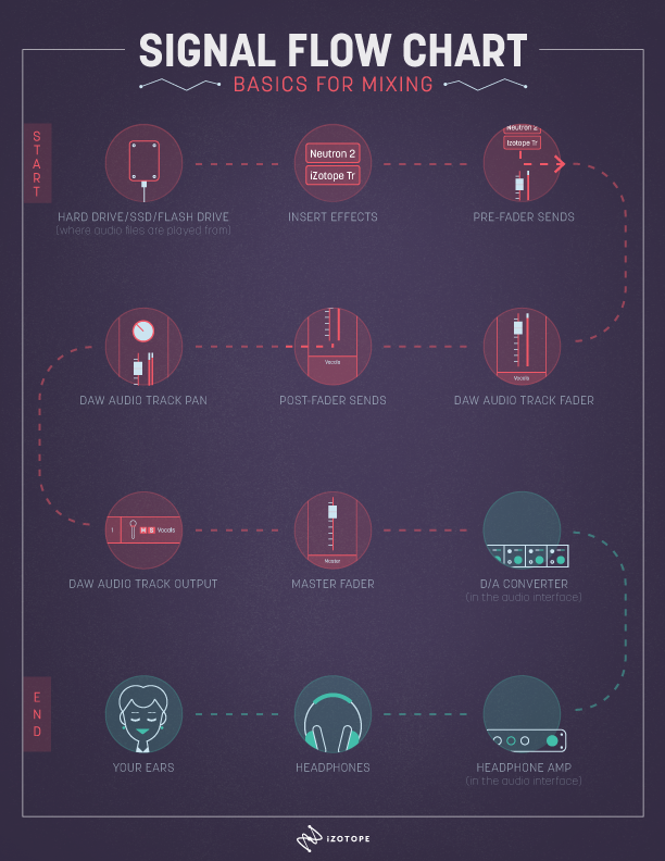
The mixing signal flow
If you take away the first six steps from the recording signal flow (because they don't apply to mixing), it is identical to the mixing signal flow!
A wildly common self-induced mixing problem is clipping. Fortunately, it can usually be avoided through a clear understanding of signal flow. For example, imagine the following scenario: an audio file that was recorded at a peak level of -2 dBFS is played through a compressor plug-in with 2 dB of gain reduction and a 9 dB boost on the output level. That is passed along to a pre-fader send at 0 dB, the track fader at -1 dB, a post-fader send at 0 dB, and eventually the Master fader at 0 dB.
Where would clipping occur? If you thought, "From the plug-in though the Master fader," you're correct! Every stage after the plug-in would be above 0 dBFS (see image below).

Clipping channel faders
How would you fix the issue? If you thought, "Turn the faders down," you're wrong! Since the clipping was caused by the gain boost in the compressor plug-in, the signal needs to be attenuated either in the plug-in or before it, which would require a region-based level adjustment.
If your DAW offers both methods, choose carefully. Lowering the signal level before the compressor plug-in would change the amount of compression, whereas lowering the compressor plug-in’s output gain would not. With any threshold-based plug-in such as a compressor, gate, or dynamic EQ, changing the level before the plug-in will definitely affect the functionality of its processing. You can use that to your advantage, but it can become a problem if you forget about it.
Lastly, it should be noted that in the floating-point processing universe we have the ability to increase levels above 0 dBFS without clipping, but the signal must be reduced before being rendered to a fixed point (24 bit) data chunk or before playback through a convertor to avoid clipping.
Conclusion
Of course, there are a myriad of signal flow variations, especially if you start using analog outboard gear or plug-ins in DSP-powered mixers. The good news is that if you feel solid and confident about signal flow in the preceding scenarios, you can run sessions more effectively and successfully create more complex configurations to suit the creative needs of you and your clients. Be comfortable with the basics first, then get fancy later on!
